
Inquiries, partnerships, and case study downloads:example@robotlyne.com
Automated Workshop Buffer Warehouse for SMT and Insertion Lines
A semi-finished-goods buffer warehouse automation concept for SMT and insertion workshops, combining stacker cranes, WMS/WCS, conveyors and AGV docking.
See how we designed this project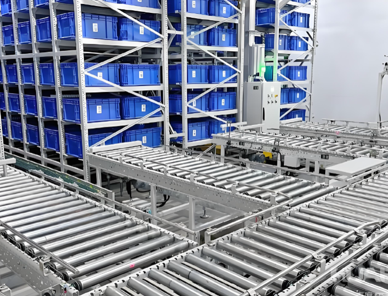
Project Snapshot
- Client Type
- Electronics Manufacturer
- Timeline
- Project plan dated 2025-12
- Deliverables
- SMT and insertion workshop buffer warehouse layout
- Stacker crane storage and conveyor docking plan
- WMS/WCS inventory and location management workflow
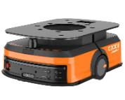
- AGV line-side docking and material transfer process
Background
Project scope
The source proposal defines an automated semi-finished-goods buffer warehouse for SMT and insertion workshops. The project covers automatic inbound storage from line-end points, downstream material pull requests, outbound delivery to production lines and line-side docking through roller equipment and AGV transfer.
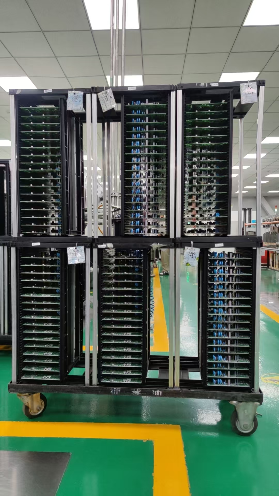
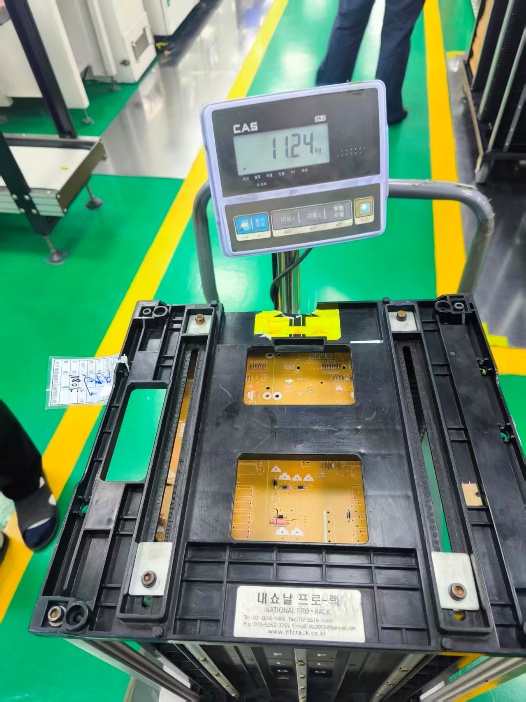
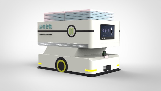
The material handled in the proposal is a magazine/carrier-type load. The stated single-unit maximum weight is 5.81 kg, with a material size of 230 x 219 x 311 mm. The upper-level customer system connects through an SRD standard API. Line-side loading and unloading use roller docking, and the AGV body is designed with four buffer positions.
Operating objectives
The upper-level system coordinates the full process, including production-line information reading, material information reading and AGV task dispatching. Buffer positions are managed as warehouse locations, including waiting, aging-in-process and aging-complete states.
The project objective is to automate semi-finished-goods storage logistics, support automatic inbound handling at line ends, allow downstream pull-based material movement and replace manual transport with unmanned vehicles. The proposal assumes a double-shift operation: one shift is 12 hours minus 100 minutes, or 10.33 available hours, and two shifts provide 20.66 available hours.
Material handling requirements
- Workshop scope: automatic inbound and outbound design for the semi-finished-goods warehouses in the insertion and SMT workshops.
- Floor height: 3.25 m.
- Handling methods: stacker crane handling, roller vehicle docking and machine-side delivery.
- Package size: 35.5 x 31.6 x 58 cm.
- Single-box handling requirement: no more than 15 kg per handled unit.
Flow volume and carrier analysis
The proposal uses customer-provided transport volume and on-site communication data. It notes that the measured transport flow is a high annual level and uses this data as the planning baseline.
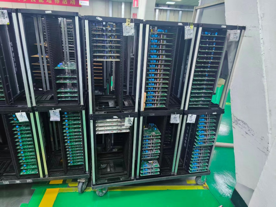
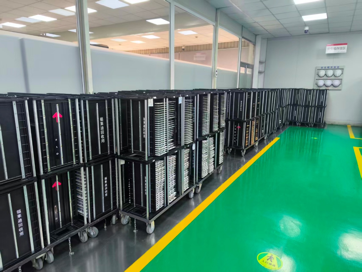
For the SMT workshop, one line can generate from 1 to 12 inbound codes, with an average of around 4 codes. One workshop generates around 30 codes across two shifts. The normal line-side warehouse state is around three full carts and one empty cart. After 100 minutes of operation, a single line produces around 33 finished-product codes, or about 8 to 9 finished carts.
For the insertion workshop, the carrier flow and storage state are analyzed separately, including the current number of loaded carts, storage zones and expected warehouse load.
Challenge
Current pain points
The proposal identifies several current-state problems in the existing warehouse operation:
- No system-driven operation.
- Low information transparency.
- Limited storage locations.
- Coarse large-location management.
- Weak expiry and aging-period management.
- Poor information coordination.
The existing process uses original bin cards and handwritten inventory registration, creating high warehouse management cost and slow feedback. Large-location management means the exact storage position is not precise, which makes finding goods and stocktaking difficult. Manual batch and expiry management also makes it hard to enforce FIFO, batch control and aging-period control.
Storage and data pressure
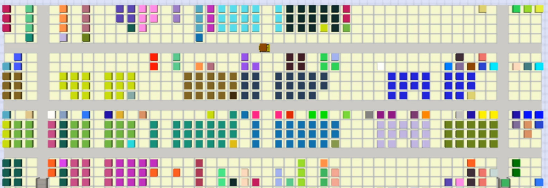
The insertion workshop inventory analysis states that four workshop areas store 236 carts of goods, including 118 carts in the first area and 112 carts in the second area. The proposal also estimates overflow goods already placed near line sides.
The SMT buffer warehouse analysis uses 120 carts per day, or 6 carts per hour. With 6 boxes per cart, the stock model reaches 238 carts and 1,428 boxes. With 128 material categories, the average stock depth is 11.15 boxes per category. The inbound flow is estimated at 34.85 boxes per hour, and the outbound flow is also 34.85 boxes per hour, creating a combined hourly flow of roughly 70 boxes.
The insertion buffer warehouse analysis uses 105 carts per day, or 5.25 carts per hour. With 6 boxes per cart, the stock model reaches 240 carts and 1,440 boxes. With 128 material categories, the average stock depth is 11.25 boxes per category. The inbound flow is estimated at 30.5 boxes per hour, and the outbound flow is also 30.5 boxes per hour, creating a combined hourly flow of roughly 61 boxes.
System and space constraints
The proposal states that floor stacking occupies workshop space and limits storage density. It also identifies low system integration and insufficient MES linkage as a source of information silos. The target design therefore needs both physical automation and inventory-system coordination.
Approach
Equipment selection
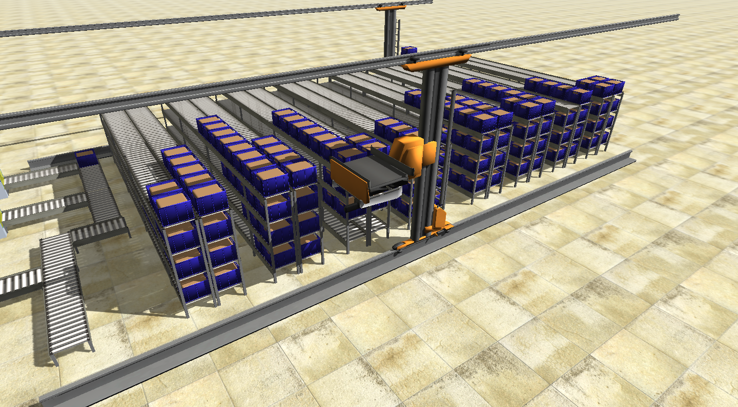
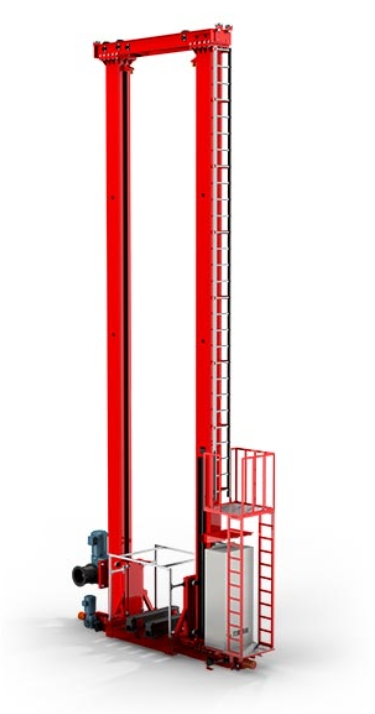
Because the area needs to store at least 128 material-code categories, the proposal concludes that a simple buffer-line method is not suitable. A shuttle system would also require each material category to hold at least 4 to 6 boxes; otherwise storage space would be wasted. Based on this analysis, the proposal selects box stacker cranes as the main inbound and outbound storage equipment.
The single stacker crane efficiency estimate is about 1 minute per box. Based on the hourly flow requirements, each workshop needs at least two stackers, and the final layout uses multiple stacker zones to support storage and transfer.
Solution architecture
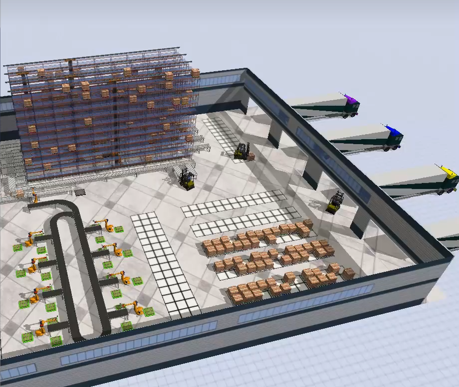
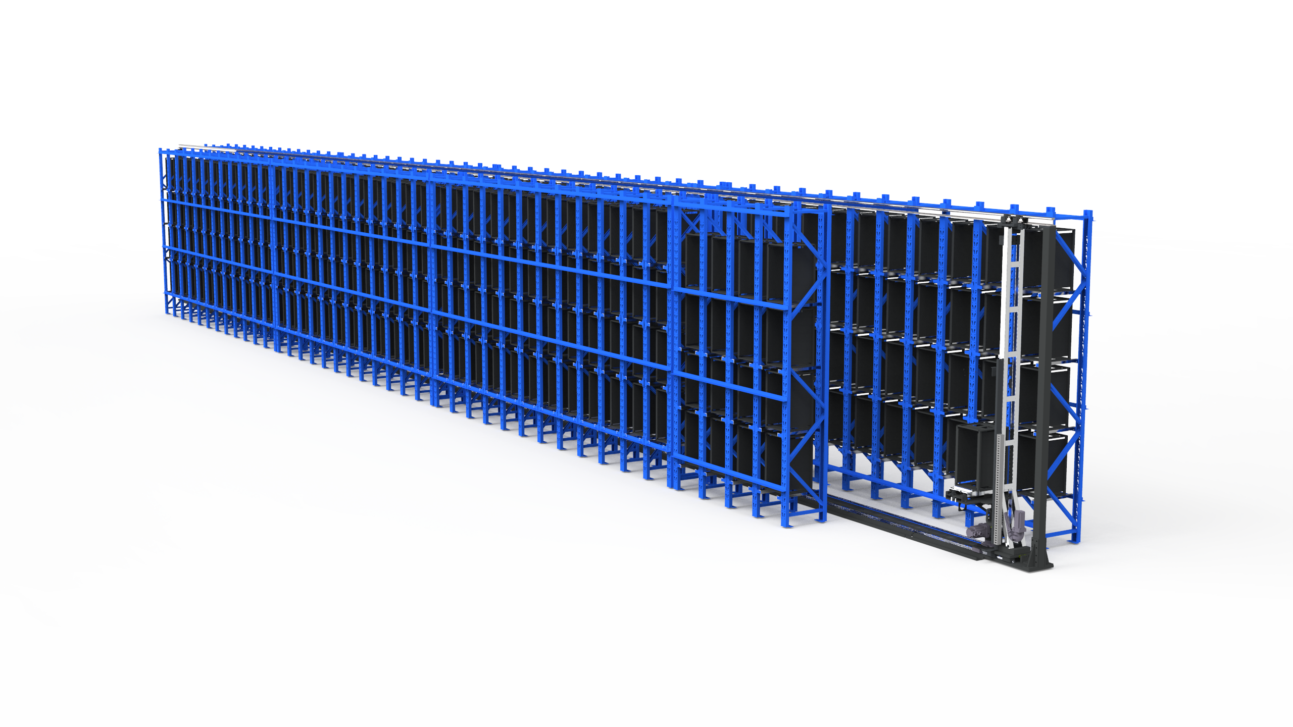
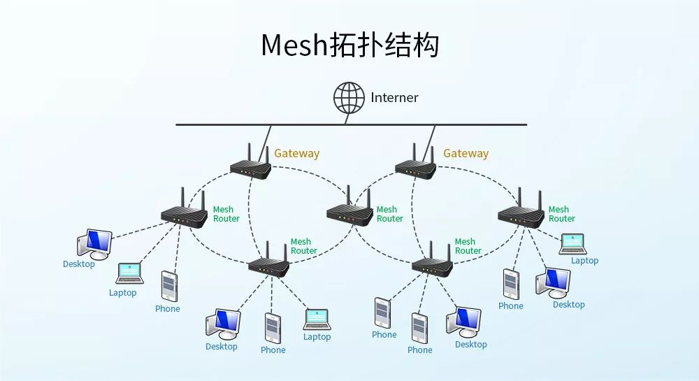
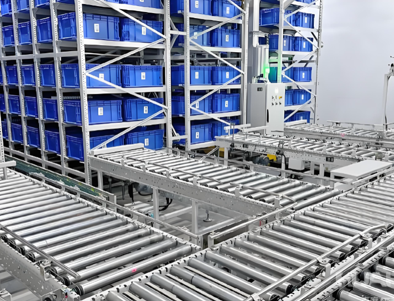
The solution uses stacker cranes for material storage, a central control system for inventory management, wireless networking for stacker communication, storage-area reconstruction, floor and fire-protection coordination, docking-area handling and AGV machine-side docking.
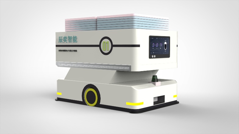
The proposal recommends unmanned vehicles that can work continuously across day and night shifts. It states that unmanned transport can improve efficiency and reduce repeated manual handling in workshop logistics.
Semi-finished-goods inbound workflow
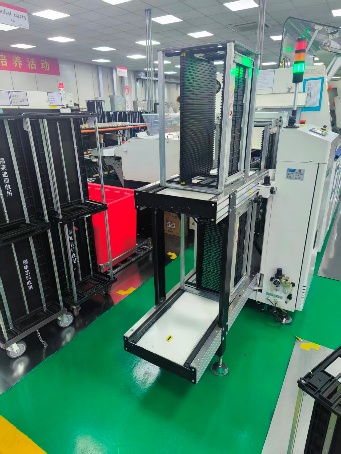
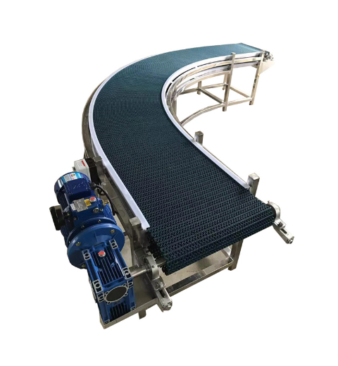
For inbound material, semi-finished goods leave the production line, transfer through conveyors and stacker-crane handling and then enter the rack storage area.
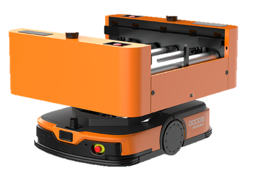
The operator scans the line code or inputs the production order number. After the last finished product on the line is scanned, the PLC detects completion at the point, and the central control system creates inventory while synchronizing the produced quantity. The system calculates the target storage area and generates an equipment task. A roller AGV transfers 1 to 2 boxes to the warehouse entry point. The system scans the material box code, binds the inventory, allocates a storage location and synchronizes the inbound completion state.
Semi-finished-goods outbound workflow
For outbound material, production calls material from the semi-finished-goods warehouse. The system receives the production order, locks inventory, calculates the target line and generates transport tasks. A roller AGV carries two boxes at a time to the line-side delivery point, and inventory removal or usage is recorded.
For SMT line-side operation, the source proposal notes long-side loading and states that each online point should have at least three buffer slots.
Empty-container workflow
The proposal also describes empty-container handling. Empty boxes are loaded manually to the buffer line, transferred through conveyors and stackers and then delivered according to the empty-box process. This gives the system a closed-loop path for both full material boxes and empty carriers.
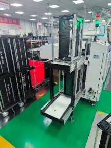
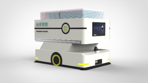
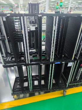
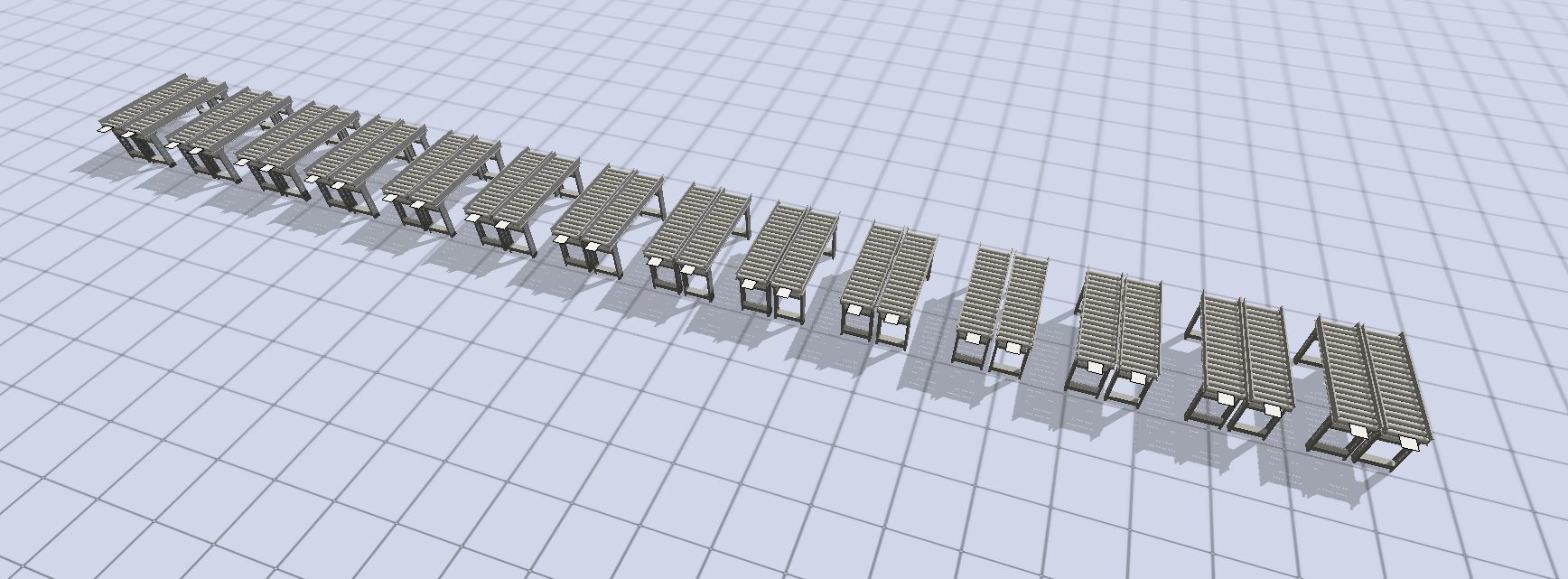
Line docking and AGV transformation
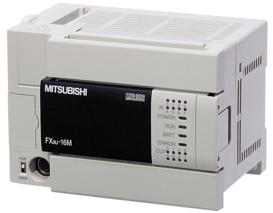
The line-docking section describes insertion-line conveyor docking. The proposal requires the PLC to support network protocols such as Siemens, Mitsubishi, Omron and Inovance. It recommends local QR-code navigation for repeated vehicle-position calibration.
The docking accuracy stack includes multi-vehicle positioning accuracy of +/- 15 mm, cargo-position deviation relative to the vehicle body of about 10 mm and an overall docking deviation of about +/- 25 mm. The guide range is +/- 30 mm. A single roller level has a minimum height of 330 mm, docking height should be unified, and one docking action can handle two boxes.
Storage layout
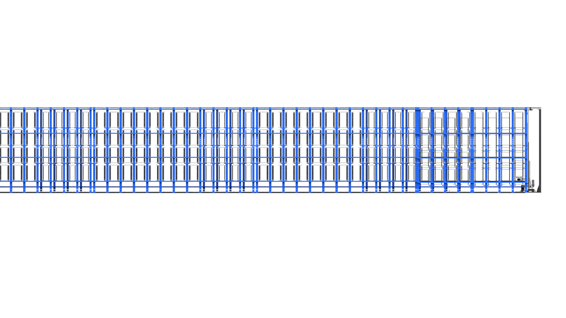
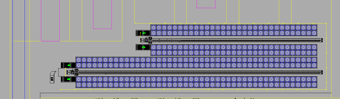
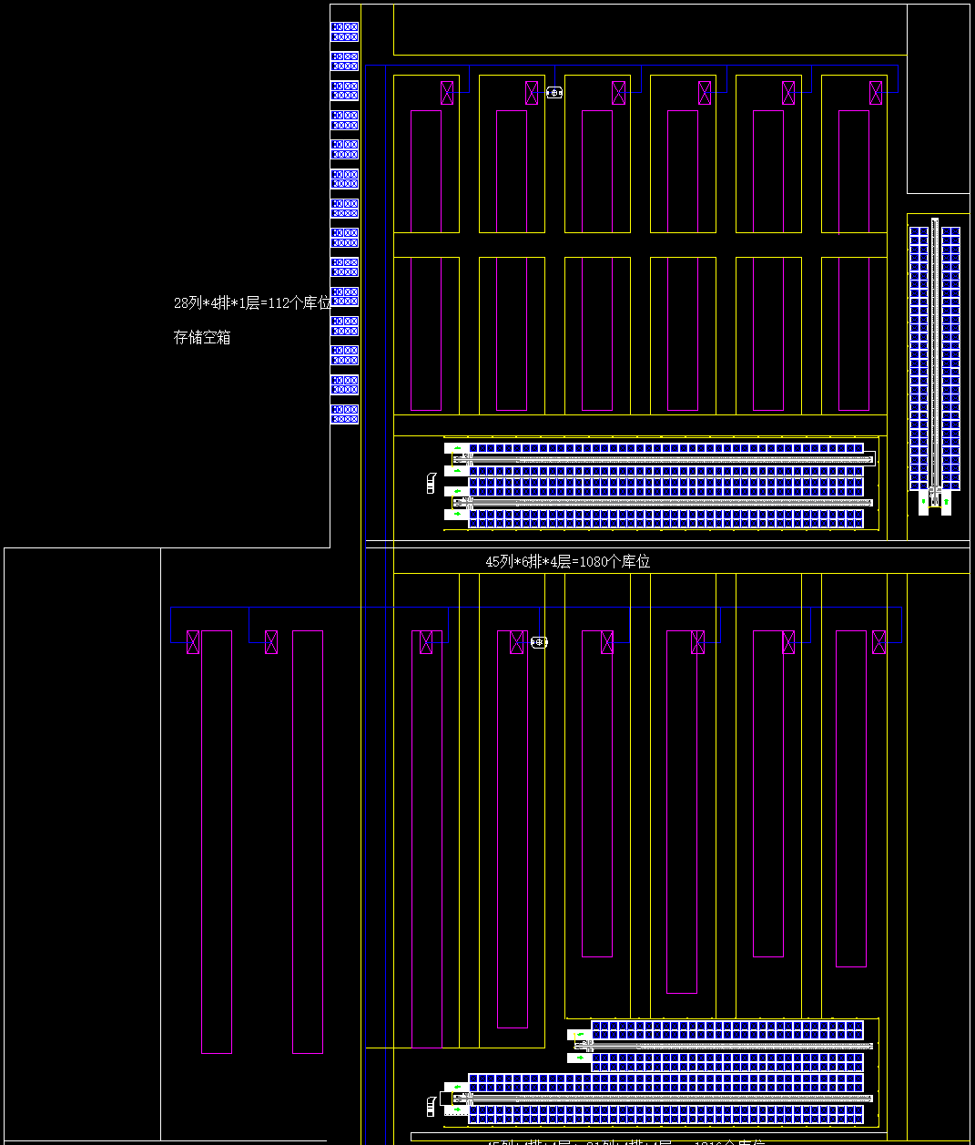
The insertion workshop layout includes a right-side storage layout with 45 columns x 6 rows x 4 levels, or 1,080 locations. The original area stored 120 carts and 720 boxes, so this area increases storage locations by 50%.
The same insertion layout also includes another storage area with 30 columns x 4 rows x 4 levels, or 480 locations. The original area stored 60 carts and 360 boxes, so this part increases storage locations by 33%. The total design provides 1,560 full-box locations. The left-side area includes 50 carts and 300 boxes adjusted for empty boxes, and the plan uses three stackers.
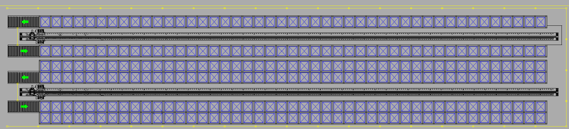
The SMT layout uses 45 columns x 4 rows x 4 levels plus 31 columns x 4 rows x 4 levels, providing 1,216 locations. The original storage area plus line-side storage had 170 carts and 1,020 boxes, so storage locations increase by 20%. The layout uses two double-deep stackers.
Stacker crane parameters
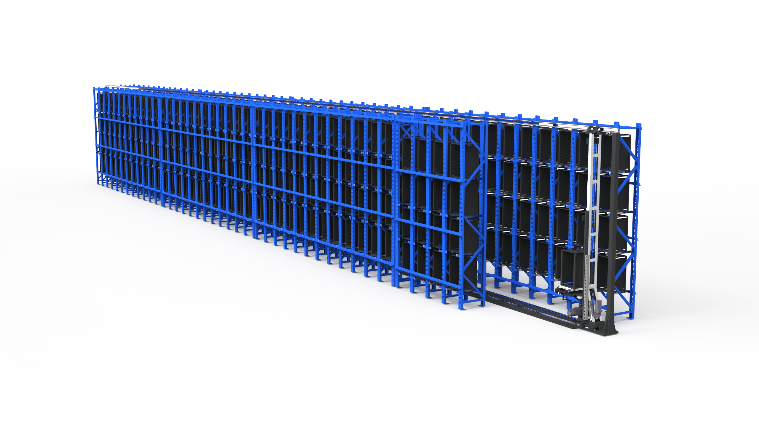
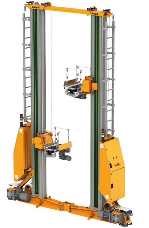
The box stacker crane is specified as a single-column floor-supported straight-travel model.
| Item | Parameter |
|---|---|
| Travel speed | 1 m/s |
| Lifting speed | 0.5 m/s |
| Fork telescoping stroke | +/- 900 mm |
| Maximum load | <= 25 kg |
| Lifting stroke | 400 to 2,390 mm |
| Travel stroke | 0 to 23,950 mm |
| Travel positioning accuracy | +/- 5 mm |
| Lifting positioning accuracy | +/- 3 mm |
| Power supply | Safe sliding contact line |
| Control method | PLC |
| Operating mode | Single / compound operation |
| Safety and sensing | Safety door, material detection and code scanning |
| Communication | Industrial wireless |
Hardware, software and service configuration
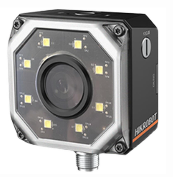
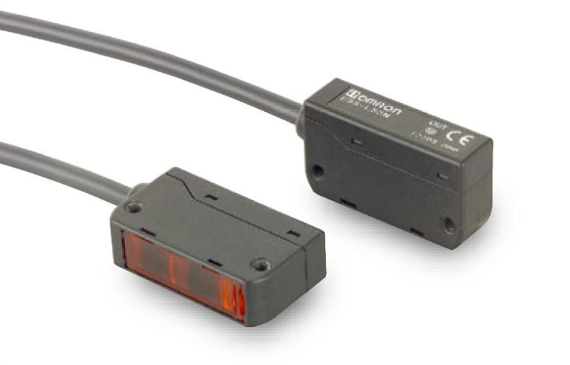
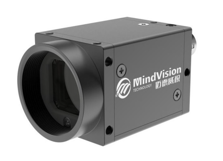
The warehouse configuration plan includes five stacker cranes, 2,776 storage locations, ten conveyors, ten code cameras, three conveyor control cabinets, three inbound/outbound terminals, safety fencing and safety locks, material access doors, a local deployment server, cabinets, optional PDA devices and wireless network equipment.
The software scope includes WCS equipment-control software and WMS warehouse-management software. The service scope includes rack installation, location adjustment, inbound and outbound testing and system-integration commissioning.
| Type | Scope |
|---|---|
| Hardware | Stacker cranes, storage locations, conveyors, code cameras, control cabinets, terminals, safety fencing, server and network equipment |
| Software | WCS and WMS |
| Service | Installation, storage-location adjustment, inbound/outbound testing and integration commissioning |
System architecture
The system design connects ERP, MES, WMS, AGV scheduling and equipment control. The proposal describes a business management layer, central control layer, execution layer and vehicle/equipment scheduling layer. It also includes RCS, WCS and a 3D digital-twin view for visual operation.
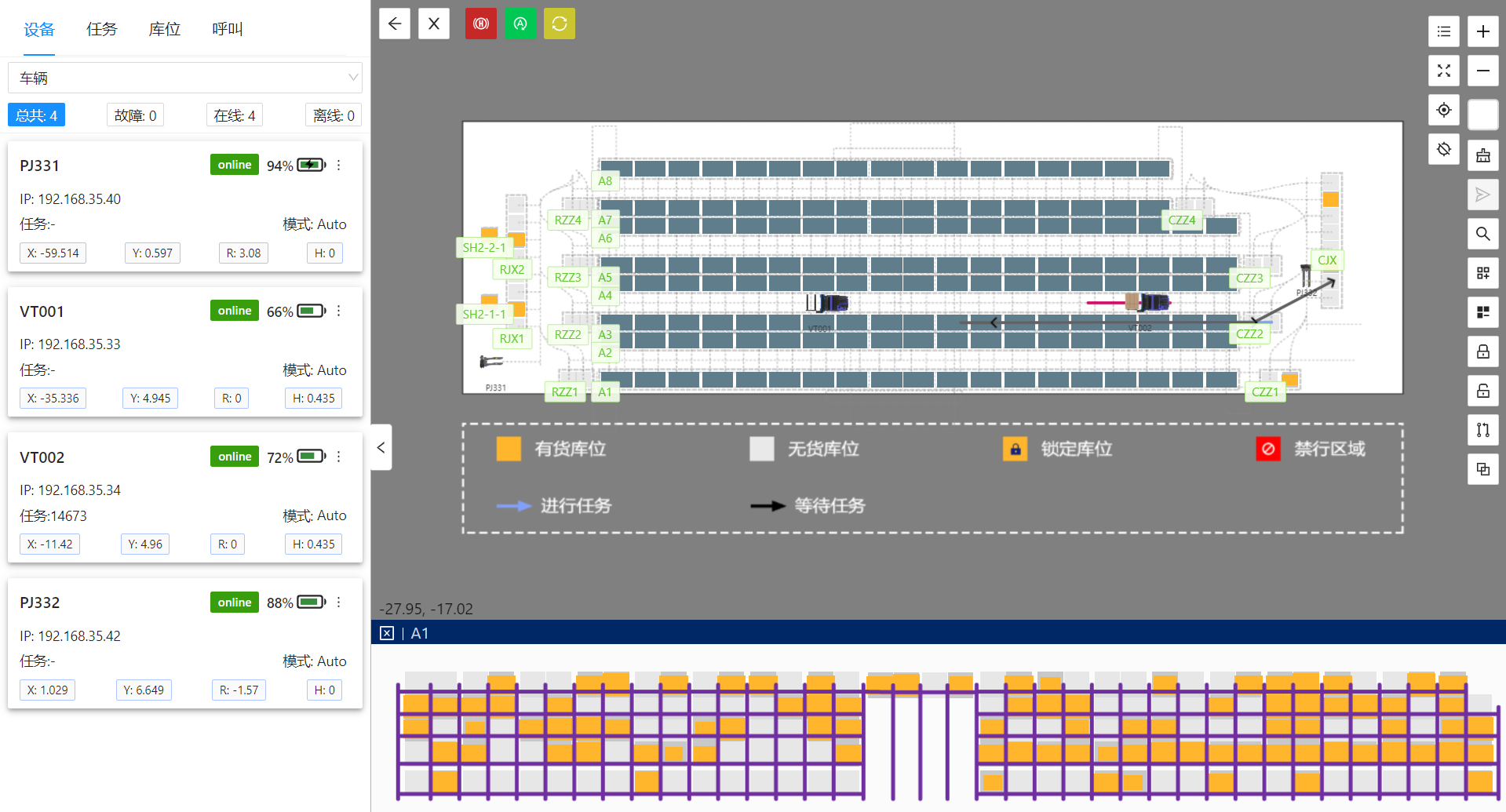
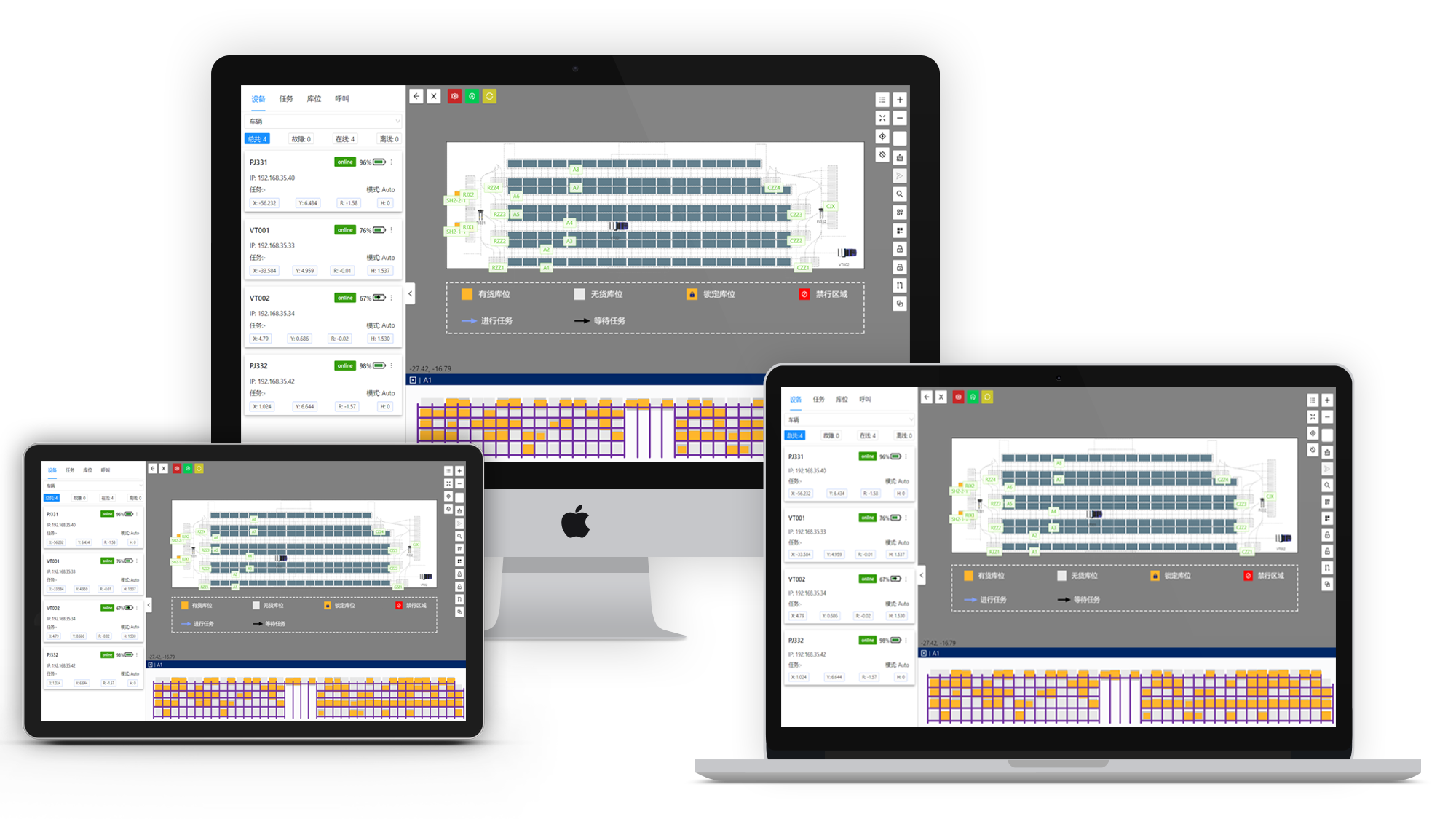
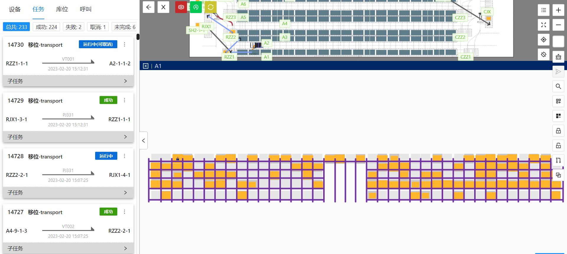
The central console supports map zooming, inventory search by material code, material name, production order and sales order, map switching, equipment management, storage-location state monitoring, location freezing, inventory management, task management, call management and arbitrary task creation.

Operator console, PDA and data acquisition
The operator console is designed for PC and tablet use. Operations managers can view system operation in real time. The system supports cluster scheduling for multiple vehicle types, global time-space path planning and scheduling for up to 100 vehicles.
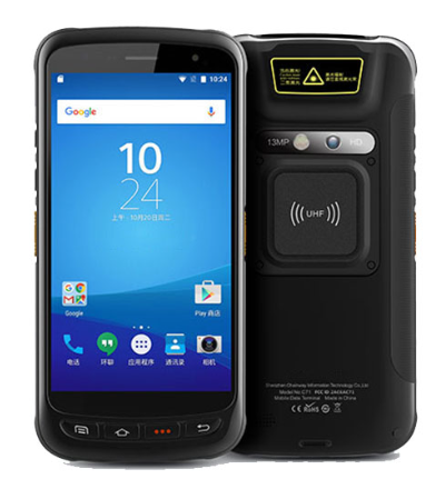
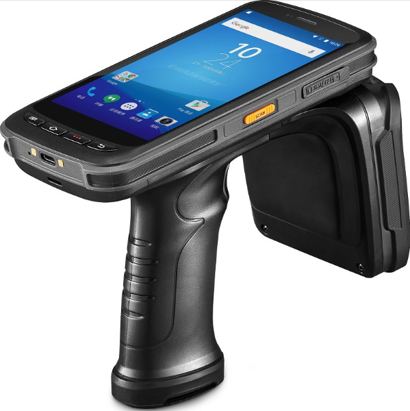
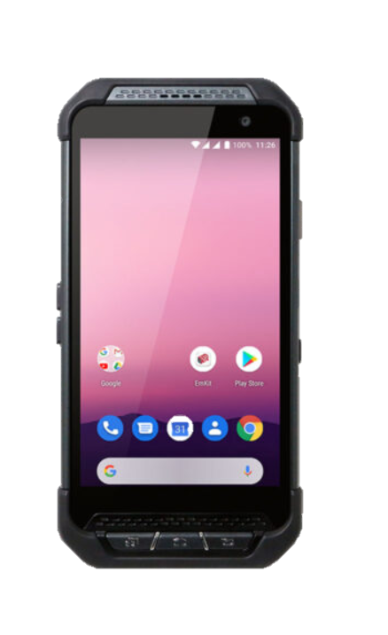
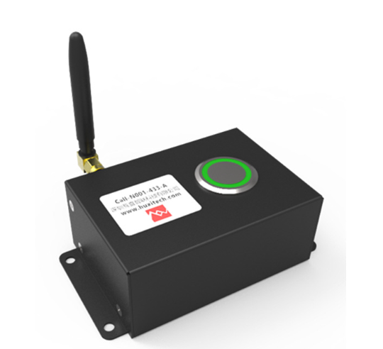
The PDA mobile module provides warehouse-management functions for mobile operators.
The data-acquisition and monitoring layer supports multiple PLC communication protocols, including MC, Modbus, Siemens S7-1500/1200/400/300, FINS TCP/UDP and other mainstream industrial interfaces. Inventory can be created through WMS/MES instruction, scanning or dynamic form operations.



Order orchestration and digital twin
The order orchestration section describes A, B and C orders, as well as instruction creation, dispatch, execution and feedback across WMS, WCS and AGV scheduling.
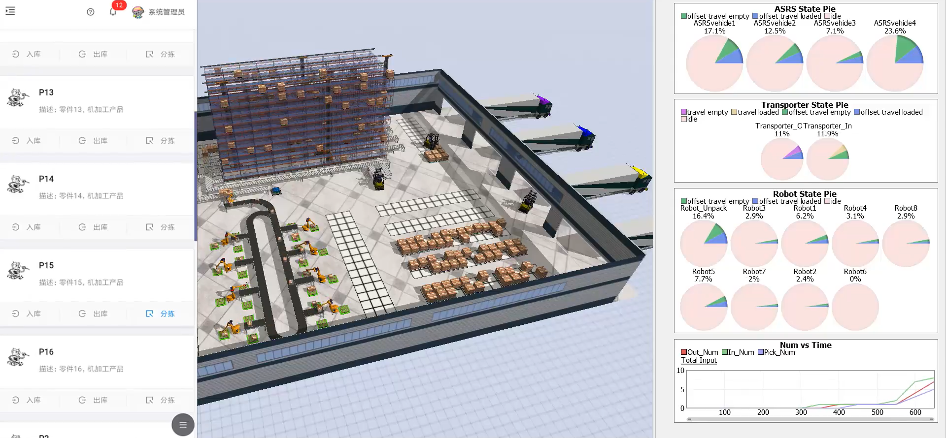
For highly automated and complex scenes, the proposal recommends a 3D digital-twin display. It states that browser-based 3D visualization can show equipment status and alarms from multiple angles without installing extra software. The 3D twin shares the same 2.5D data foundation and can be opened through a web browser.
Site and network requirements
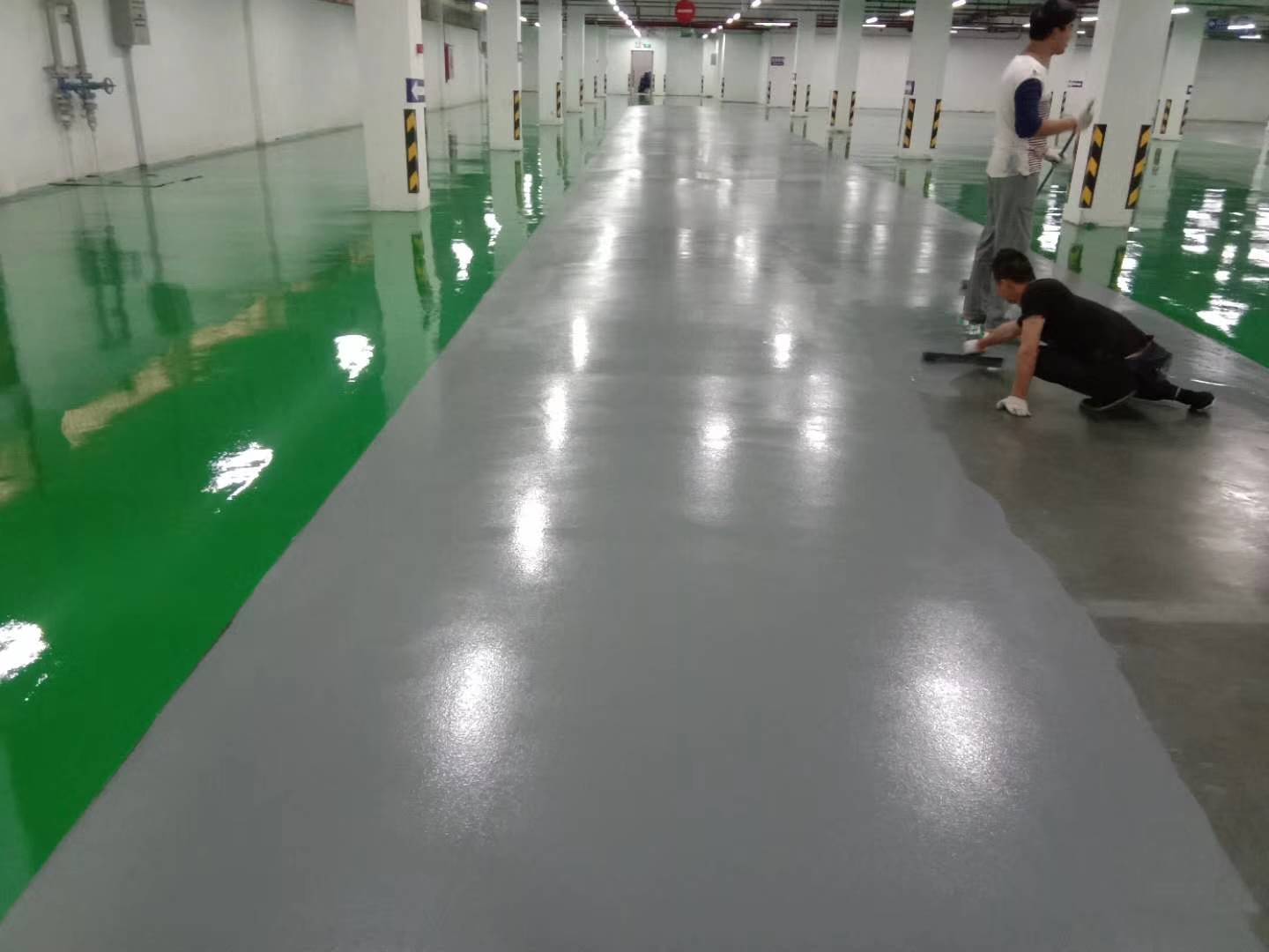
The site environment section requires a flat, undamaged and clean floor without hollowing, oil, glue or long-term liquid contamination. The running-track installation foundation must meet flatness requirements, and the floor must be able to support the relevant equipment and rack loads.
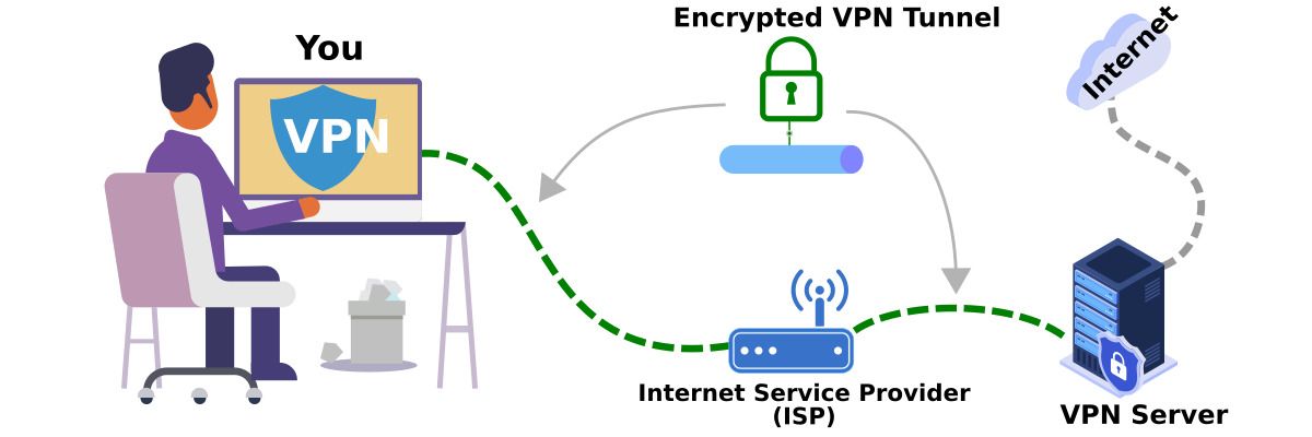
The network and VPN section states that in the early project phase, the customer-provided server should be able to access the external network for WES and RSS software-environment installation. For operation and maintenance, the maintenance team needs reliable remote access to the system LAN for diagnostics and support.
Outcome
Expected system benefits
The proposed system changes the warehouse from manual card-based management to system-controlled inventory, equipment execution and visualized warehouse operation.
The expected benefits include:
- Full-process system control.
- Transparent inventory and task information.
- Increased storage locations.
- More precise one-box-one-location management.
- Batch, FIFO and expiry-period management.
- Multi-system collaboration with MES and upstream systems.
- Automated inbound and outbound handling through WMS/WCS and equipment control.
Capacity and operating improvements
The storage layout increases capacity in the same workshop footprint by using four-level box storage. In the insertion area, one designed zone increases capacity by 50%, another increases capacity by 33%, and the full-box layout reaches 1,560 locations. In the SMT area, the layout reaches 1,216 locations and increases storage locations by 20%.
The system records location-level inventory, binds inventory automatically during inbound, updates inventory in real time and lets authorized users locate materials through the system. Automated equipment replaces floor stacking and repeated manual transport while supporting line-side material pull and warehouse execution.
Deployment and service plan
The project implementation plan is organized by week, beginning with contract signing, then solution confirmation, design, procurement, manufacturing, installation, commissioning, trial operation and acceptance.
The service section states a 30-minute response after receiving after-sales requirements. Remote technical support is attempted first; if remote support cannot solve the fault, on-site support is planned within 24 hours during the warranty period.
The proposal also states the company mission, vision and values: helping customers solve manufacturing pain points through automation, becoming a trusted partner in intelligent manufacturing, and focusing on customer achievement, employee growth, teamwork and continuous innovation.
Project Feedback
Share a short review of this case study or tell us what kind of automation project you want to compare it with.
No published reviews yet.